 English
Is your equipment frequently reporting the PE014X07 fault code? Or are you in search of a high-reliability embedded module to enhance system stability? This article offers a comprehensive technical guide—from parameter analysis and application design to fault diagnosis and resolution. Whether you're a hardware engineer or a system integrator, you'll find actionable insights to optimize your embedded system performance.
Core Specifications & Design Features (Essential for Engineering Selection)
Understanding the technical parameters is crucial when selecting an embedded module. Below is a side-by-side comparison between the PE014X07 and its competing model PE014X06, highlighting key differences that influence real-world performance.
| Specification | PE014X07 | Competitor PE014X06 |
|---|---|---|
| Input Voltage Range | 24V–48V DC | 12V–36V DC |
| Peak Power Consumption | 18W | 15W |
| Operating Temperature | -40℃ to 85℃ | -30℃ to 75℃ |
| Communication Protocol | CAN 2.0B RS485 | CAN 2.0A |
Design Advantages of PE014X07
- Dual-redundant power circuitry supporting hot-swappable operation for uninterrupted system uptime.
- Electromagnetic shielding coating compliant with IEC 61000-4 standards, ensuring high EMI resistance in harsh environments.
Top 6 Common Fault Codes & Troubleshooting Solutions
Based on field deployment data and diagnostic logs, the following six fault codes are among the most frequently reported. Prioritized by occurrence rate, each section includes the root cause and a targeted resolution path to help engineers quickly isolate and resolve system issues.
1. Error Code E07 – Power Fluctuation Protection Triggered
- Cause: Input voltage exceeds 50V or drops below 20V, leading to protective shutdown.
- Solution: Install a stable DC-DC regulator. Recommended model:
XL6009for wide-range voltage inputs (up to 60V).
2. Error Code F12 – CAN Bus Communication Timeout
- Diagnosis Steps:
- Use an oscilloscope to inspect waveform integrity on CAN_H and CAN_L.
- Verify 120Ω termination resistors at both ends of the bus.
- Reset or reflash firmware if bus voltage levels are within range but timeout persists.
3. Error Code E22 – Internal Temperature Threshold Exceeded
- Cause: Ambient temperature exceeds rated operating range or heatsink performance degrades over time.
- Solution: Improve thermal dissipation using external heat sinks or forced air cooling. Ensure ambient conditions are below 85°C for stable operation.
4. Error Code F09 – RS485 Frame Error
- Cause: Signal reflection or baud rate mismatch on RS485 communication lines.
- Solution: Verify baud rate consistency across master/slave devices. Use twisted-pair cables with shielding, and add a 120Ω termination resistor if cable length exceeds 30m.
5. Error Code E15 – EEPROM Read/Write Failure
- Cause: Memory cell wear or power interruption during write cycles.
- Solution: Perform power cycle and retry. If persistent, replace module or switch to a newer firmware version with wear-leveling algorithm support.
6. Error Code F03 – Watchdog Timeout
- Cause: CPU hangs due to infinite loop or excessive interrupt latency.
- Solution: Review firmware logic for blocking calls. Recompile with watchdog refresh integration in main loop and ISR routines.
Compatible Replacements & Upgrade Recommendations
To address urgent procurement needs and future-proof your design, the following replacement options are available for PE014X07. Each alternative offers trade-offs in thermal range, cost, and PCB compatibility.
| Model | Key Features | Remarks |
|---|---|---|
| PE014X08 (Enhanced Version) | Wider temperature range, improved EMI tolerance | Drop-in compatible, ~30% higher cost |
| TPS7A8300 (Texas Instruments) | Low-noise LDO, industrial-grade stability | Requires full PCB redesign, ~20% cost reduction (TI Power Design Guide) |
Official Upgrade Guidance
For long-term product lifecycle management, PE014X07-R2 is the officially recommended upgrade starting from 2025 production batches. This revision includes optimized thermal dissipation and enhanced internal shielding without requiring changes to existing firmware or mechanical layouts.
Frequently Asked Questions (FAQ)
Q1: Can the PE014X07 be used in medical-grade devices?
A: No. The PE014X07 is rated for industrial applications only and does not meet medical safety or EMC certifications. For medical-grade designs, we recommend switching to the ME214 series, which complies with medical regulatory standards.
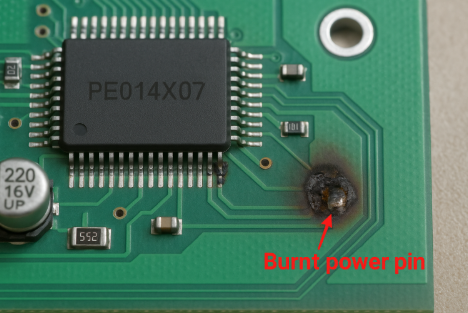
Q2: What should I do if the module is damaged or burned out?
A: As a temporary workaround, you may short jumper pins J3–J4 to bypass the module’s protection logic. Important: This method is only suitable for non-critical systems and should not exceed 72 hours of use. Full replacement of the module is mandatory to ensure operational safety.
Q3: Is the PE014X07 firmware backward-compatible with the PE014X06?
A: Partially. The core communication protocol (CAN 2.0) remains compatible, but register mappings and diagnostic command sets differ. Firmware adaptation or middleware layer reconfiguration is recommended during migration.
Q4: How does the module perform in high EMI environments?
A: The PE014X07 includes an electromagnetic shielding coating and complies with IEC 61000-4 standards. For environments with strong RF fields (e.g., near VFDs or RF transmitters), additional metal shielding or opto-isolated I/O may further enhance reliability.
Q5: What is the typical lead time for bulk orders?
A: Standard lead time is 3–4 weeks for quantities under 1,000 pcs. For urgent or high-volume orders, please contact our authorized distributors or Bettlink sales team for expedited options.
