English
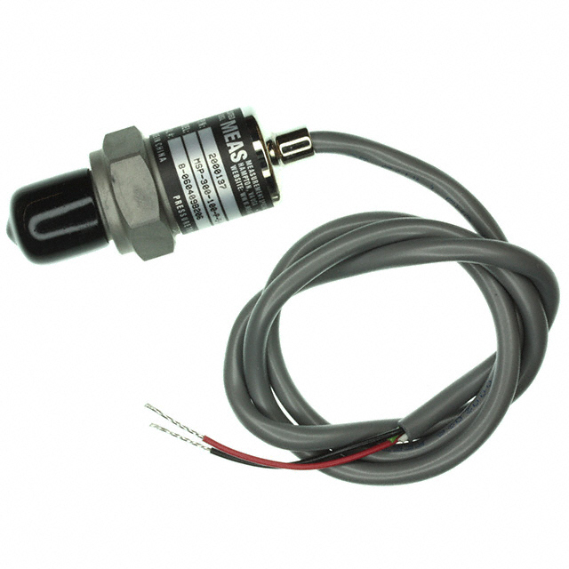
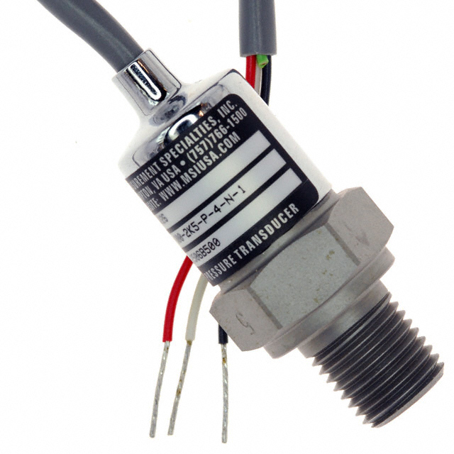
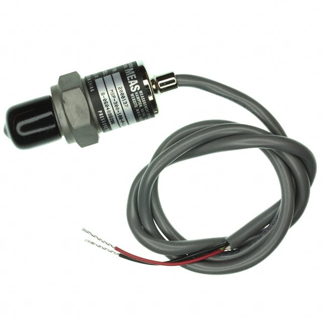
Experiencing measurement drift or unstable pressure readings in hydraulic or process control systems? The M3051-000005-100PG by TE Connectivity is a high-reliability pressure transmitter engineered for harsh industrial environments. With robust construction, precision signal conditioning, and long-term stability, it is designed to meet the demands of mission-critical automation systems.
Core Specifications & Selection Criteria (Engineer’s Must-Read)
| Parameter | M3051-000005-100PG | Comparable Model: M3051-000005-10KPG |
|---|---|---|
| Operating Pressure | 100 PSI (689.48 kPa) | 10,000 PSI (68,948 kPa) |
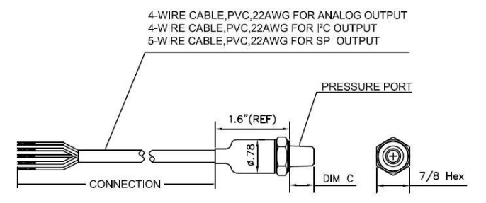
| Output Signal | 4–20 mA analog current | 1–5 V voltage output |
| Accuracy | ±1% Full Scale (FS) | ±0.5% FS |
| Supply Voltage | 9–30 V DC | 5–30 V DC |
| Operating Temperature | −20°C to 85°C | −40°C to 125°C |
| Pressure Type | Vented Gauge | Absolute |
| Package | Cylindrical threaded housing | Same series |
Design Advantages
- Temperature Compensation: Full-range accuracy deviation ≤ ±0.1%, minimizing thermal drift in dynamic environments.
- Overpressure Protection: Rated for up to 200 PSI (1378.95 kPa), preventing damage from pressure surges or spikes.
- IP67 Protection: Threaded 1/4" NPT port with direct cable termination ensures reliability in wet, dusty, or oily environments.
Top 4 Industrial Applications & Circuit Design Insights
1. Real-Time Monitoring in Hydraulic Systems
Challenge: Conventional sensors suffer from output drift under high-pressure surges.
Solution: Integrate an RC low-pass filter (10 μF 100 Ω) to suppress output noise. Ensure the ADC sampling rate is ≥ 100 Hz for accurate signal capture.
Wiring Diagram: Vcc → TVS Diode → M3051 → 250 Ω Precision Resistor → GND
(The resulting voltage signal across the resistor is 1–5 V, proportional to pressure.)
2. Valve Position Feedback in Process Control
Challenge: Temperature fluctuations in steam environments distort pressure readings.
Solution: Leverage the sensor’s internal temperature compensation feature—eliminating the need for external RTDs and reducing BOM cost by approximately 30%.
3. Hydraulic Safety Monitoring in Construction Machinery
Challenge: High vibration causes cable loosening or intermittent signal loss.
Reinforced Design: Replace direct-wired connectors with M12 aviation-grade connectors, rated for vibration resistance up to ≥ 10 g RMS.
4. Flow Rate Estimation in Water Treatment Pumping Stations
Calculation Formula:Q = k × ΔP
Where:Q = Flow ratek = System constant (based on orifice and pipe dimensions)ΔP = Differential pressure measured by the M3051 sensor
Top 3 Common Failures & Diagnostic Workflow
Issue 1: Output Stuck at 4 mA or 20 mA
Possible Causes: Abnormal power supply or internal sensor disconnection.
Troubleshooting Steps:
- Verify supply voltage is within 9–30 V DC.
- Measure resistance from output to ground (normal range: 50–500 Ω).
- Gently tap the sensor housing and observe output response—any transient change may indicate internal mechanical damage.
Issue 2: Output Drift Exceeding ±2%
Root Causes:
- Temperature compensation failure (commonly above 80°C).
- Crystallization or blockage in the pressure port due to fluid residue.
Solutions:
- Install a heatsink or apply active cooling (fan-assisted airflow).
- Periodically clean the pressure port using isopropyl alcohol to dissolve deposits.
Issue 3: Response Delay Exceeds 100 ms
Root Cause: External RC filter capacitor too large (e.g., >1 μF).
Optimization: Replace with a 100 nF ceramic capacitor (C0G type) to reduce response time to ≤ 20 ms.
Diagnostic Flowchart:
- Check supply voltage stability
- Validate output load resistance
- Inspect mechanical integrity (shock, cracks, housing)
- Assess environmental conditions (temperature, vibration, contaminants)
Alternative Models & Selection Decision Tree
| Model | Key Differences | Recommended Use Case |
|---|---|---|
| M3051-000005-500PG | Rated for 500 PSI | Medium-pressure pneumatic systems |
| M3041-000006-01KPG | 1–5 V voltage output | Short-distance signal transmission (<10 m) |
| Honeywell 26PCFFA6G | Absolute pressure, ±0.25% accuracy | Vacuum chamber pressure monitoring |
Selection Guidelines
- Pressure Range: Choose a sensor where the working pressure ≤ 80% of the sensor's full-scale rating.
Example: For an 80 PSI system, select a 100 PSI-rated sensor. - Output Type:
- For long-distance transmission or EMI-prone environments: Use 4–20 mA current loop output (e.g., M3051 series).
- For cost-sensitive or PCB-level designs: Use 1–5 V voltage output models (e.g., M3041 series).
PCB Layout & Signal Integrity Best Practices
Power Supply Decoupling
- Place a 10 μF tantalum capacitor in parallel with a 100 nF ceramic capacitor close to the Vcc pin (within 5 mm).
Output Signal Interference Protection
- Use twisted pair shielded cables for analog output transmission.
- At the receiver side, apply an RC low-pass filter with a cutoff frequency of 50 Hz to suppress high-frequency noise.
Grounding Strategy
- Implement star-point grounding to eliminate ground loop interference between analog and digital domains.
- Use a 0 Ω resistor bridge between analog ground (AGND) and digital ground (DGND) for controlled separation and layout flexibility.
Frequently Asked Questions (FAQ)
Q1: Can the M3051-000005-100PG directly replace the M3051-000005-250PG?
Yes. As both models belong to the same series, the only difference is the pressure range. No circuit modification is required, but zero-point recalibration is necessary to ensure accuracy.
Q2: Is this sensor suitable for use in medical devices?
No. The M3051 series does not carry medical-grade certifications. For medical applications, use TE’s M3200 series, which is ISO 13485 compliant.
Q3: How can I calibrate the sensor on-site?
Field Calibration Procedure:
- Expose the pressure port to atmospheric pressure and adjust the zero potentiometer until the output reads exactly 4 mA.
- Apply full-scale pressure (as specified) and adjust the gain potentiometer until the output reaches 20 mA.
Authoritative References
- TE Connectivity Official Datasheet (M3051 Series):
https://www.te.com/usa-en/product-M3051-000005-100PG.datasheet.pdf
Includes detailed specifications, pressure ratings, electrical interface, and calibration procedures for M3051-000005-100PG and related models. - IEC 61000 Electromagnetic Compatibility Standards:
https://webstore.iec.ch/publication/4202
Defines immunity requirements and test procedures for electronic devices operating in industrial electromagnetic environments. Relevant to signal integrity and EMC design in sensor systems.